Content Type
Profiles
Forums
Downloads
Gallery
Events
Articles
Everything posted by Mayhem
-
I got my Son Portal 2 for $7.50 and Garry's mod for the both of us for $2.50. Haven't decided if I'm going to get DCS-A10 and Operation Arrowhead yet.
-
Ok, don't know how good it really is though as I just spent about 20 minutes on it and haven't really done much testing. As I said, from what little testing I have done, it looks pretty good on some maps but others not so much. I hadn't used this mod before tweaking it so I don't really know what issues are inherent to the mod and what ones I might have induced. I'll be working on it some more in the next day or two and won't be satisfied till its almost perfect. Give me some input as to what needs attention. Tested it on several stock maps and its looking good. However tested it on Iwo Jima and not looking so great. From the little bit of mission building I have done the weather is always set in the mission builder however its looking like different maps handle the weather settings differently to some extent. Looking at Iwo Jima though, it would seem that a different method of cloud population is being used based on the crappy look of them compared to other maps. In this mod there are 2 main cloud textures with several clouds modeled on in each. One is a 1024x1024 .tga and the other a 512x512. I'm thinking the maps that the clouds look good on are using the higher res textures while Iwo Jima would appear to be using the low tex clouds. I'm thinking this is partially responsible for the crappy results on Iwo but it also seems that the clouds on Iwo are composed in a somewhat different manner then on some others maps as in there doesn't seem to be as many overlapping cloud textures used to create a cloud. That and it is trying to position these fewer (and lower resolution mind you) layers in a cleaver way to give the clouds the kind of volume that you get with using more and higher res layers like on some other maps. The scheme seems to have poor results in comparison. Still fiddling so don't string me up if they look a bit shotty on some maps. Currently your mileage may vary.
-
By request, Big Clouds modified my your's truly. Basically the same things I did to the Modded Clouds Lite mod. Still a bit beta-ish so if you notice some issues I'm working to fix them. I think some maps however just have the clouds done or placed badly as these clouds look pretty good on most maps but on some they are a bit glitchy like Iwo Jima. Please provide feedback. http://dangerdogz.com/forums/files/file/588-clouds-big-v21a-modified7z/
-
Man, that had to suck. At least he made it down in one piece more or less.
-
I wonder what the reasoning was behind the changeover from the linked control yokes? I guess what they say is true. "If it ain't broke, don't fix it."
-
Hello Dogz, just wondering if anyone of you would be interested in purchasing some of my hardware? I'm considering selling an AMD Athlon 64 X2 7750 Kuma 2.7GHz Socket AM2+ 95W Dual-Core black edition Processor. The title says Athlon but its actually a first generation Phenom with 2 cores disabled. There is a fairly high possibility of unlocking the extra 2 disabled cores with the right motherboard type but I've never tried this. The chip easily OCs to 3.2Ghz with no voltage increase necessary and just a multiplier adjust. Extremely stable. I'm also considering selling my current processor, mobo, and memory. An AMD Phenom II X4 840 3.2GHz Socket AM3 95W Quad-Core Processor , a Foxconn A78AX-S AM2+/AM2 AMD 770 ATX AMD Motherboard don't let the name fool ya its been a great board, and G.SKILL 4GB (2 x 2GB) 240-Pin DDR2 SDRAM DDR2 1066 (PC2 8500) Desktop Memory . It's been a great system. Plays everything well including ROF. All in perfect working order and rock solid stable. Both processors will work in the motherboard. Not at the same time of course. PM me an offer, I'd like to sell one of the CPUs, mobo and memory as a set if possible.
-
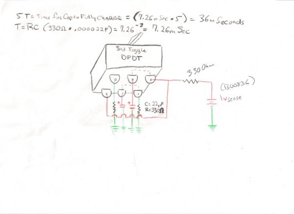
Thank you Sir, nice to be vindicated. Sorry for the inconvenience but if you're happy, I'm ecstatic. You are to be commended for deciphering my chicken scratch of a schematic. Glad to be of service, especially where Dogz are involved. Let me know if any issues arise, which hopefully won't.
-
Yeah, every time I see one I'm just taken back by what a fantastic machine they are regardless of the era. These things will still be amazing a thousand years from now. Truly timeless awesomeness.
-
Shh Our place used to be a farm, it still has 3 phase - not that we use it yet Oh, the sheep are going to have a ball with it then.
-
That looks like a Kuka robot, possibly a KR 1000 L950 TITAN PA painted black . This is very similar to the Fanuc robots I worked on at Dell. This robot could easily be in the $150k or so range with it's heavy lifting capacity and 6 axis. Robotics company often offer a range of upgrade options on their products and the redundant safety features and singularity avoidance would be a must on anything that a human being will be strapped to. I find it funny, is that Google earth flight simulator? Very neat concept however I don't know if I would be trusting any machine capable of grinding me into the floor at 2000lbs of force to not have a spontaneous brain fart though. Well, not with what I've seen before. Oh, and if you want one, you're going to have to get your house wired for 480 triple phase power which might be a problem is some areas.
-
Well in that case you can try the suggestions I mentioned in my previous post above. Try a second resistor in series and then parallel with the first resistor. Then try a second cap in series and parallel with the first cap. If that does help you can find or buy a couple of small inductors (the kind that looks like the small non-polar caps) to try to filter out the flicker. The inductor will keep the resist the change in current in the circuit but this might also effect the discharge time of the cap a bit though maybe not enough to break functionality. There still might be a problem if you try to use the circuit in a matrix config. You can try it though but if it doesn't work out you will probably only be able to use this method in a direct connection config which will limit your buttons to 12 switches if you can get the rows working.
-
Ah, rgr that, yes I see sorry. I thought you would have no problem using both columns and rows but this appears to not be the case. I see what Leo was talking about now. He's scanning the columns and rows in the matrix just like memory, polling for continuity. It may be that the reason the columns seem to be working is that they are oscillating fast enough to fool your eye into thinking the light goes out after the initial pulse when in reality it is just flashing at such a speed and duty cycle that you can't see it blinking. If the rows are strobing slow enough the flickering my become visible to the eye. In this case it may be more of a pain in the tail then it's worth. Before going with the BU0836 though I would run it past Leo and see if it will work properly on that board. Like I said before, not as simple a problem as it first appears. If you do have to go with the X board hopefully you can return your BU0836 or use it for another project. Sorry this doesn't seem to work out on this board but you may be right and hopefully the X board will function in a more co-operative manner but once again I would check first. To my knowledge you can connect several boards together and perhaps have them show up as one USB device though I don't know if they have to be the same model board or not. Hopefully you will have a use for the board you already possess. If not I or some of the other Dogz may be interested in it so you can get your money back.
-
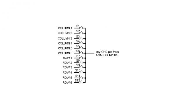
No I would use the digital ground pins. While Ground is supposed to be common there can be differences in potential depending on how things are hooked up internally. Leo sent me a reply as well. Hi Robert, BU0836 uses high frequency pulses to check resistance of switches connected to its digital inputs. THis is why your analogue RC circuit does not work well. What are you trying to do? Often it is easier to use external mapping software to create commands based on switch transitions. Check these: Autohotkey http://www.autohotkey.com/ SVMapper Link 1 or Link 2 JoyToKey http://www.mehdiplugins.com/herewedown/jtk379en.zip Alternatively, consider a switch as 1/2 of rotary encoder. COnnect switch to button 1 input and leave button 2 not connected. Use encoder setup utility from BU0836X to setup encoder mode 1:1 on buttons 1&2 and you will have pulse generated on B1 when you close the switch and pulse on B2 when you open it. If you have three position switch, connect it to buttons 1 and 3 and set up two encoders, etc. Thanks Leo From what he says here you can set up the board in "encoder mode 1:1". Says you can connect a switch to input 1 and leave input 2 unconnected and the board will generate pulses based on the switch position. Not sure if that setup will work with a matrix but if not sounds inefficient. It seems odd to me that he would be using high frequency pulses to detect buttons states but this is probably how the board is able to detect whether or not a button or switch is actually attached so it shows up in the control panel before you have pushed anything. I'm thinking since the columns are working ok we can find a workaround for the rows but it may require a little bit of experimentation. First off, start using the digital grounds for the digital inputs just to eliminate any issues with that. Test it first on the columns to verify that its working right then switch to the rows. The problem is with the high frequency variations in voltage you essentially have some amount of AC bypassing the capacitor. The cap will block DC when fully charged and that is the principle we're using to generate a single pulse. But if there is a biased high frequency signal on the DC voltage the cap will remove the biasing but the AC will still pass. Its looking like with a steady and solid DC coming from the board the circuit will work fine and is on the columns for whatever reason but with some amount of AC on the row (or at least enough to cause a problem as compared to the columns) the circuit is not able to cope with that. There may very well be some AC signal on on the column voltage as well but its frequency or biasing is such that it is not negatively effecting the capacitive charging circuit. We can probably make a small modification to the rows that will fix the issue but I need to think for a second to come up with something. I think we should use an inductor to smooth out the high frequency AC and see what happens. Inductive components like coils or inductors have a resistance to AC called reactance. Reactance is to AC what resistance is to DC. The inductor will resist the high frequency variations and produce a smoother DC signal. I'm not exactly sure how this the board will respond to this but its worth a shot. I'll tell you what I am going to do, I have an oscope, so I will open up my switchbox and check the output of the columns and rows to see what difference there is in the voltage sources. This will give us a better insight into how to work around the problem. For you however in the meantime do this first, using the digital ROW ouput and ground pins, try adding another resistor in series with the resistor in the circuit and see if that helps, if not remove that extra resistor and add it in parallel to the resistor in the circuit. What this will do is increase and decrease respectively the resistance in the circuit and change the charging time of the capacitor. This should change the line voltage and in turn the biasing of the high frequency AC which may have an effect on the output. If that fails to solve the issue you can also try adding another capacitor in series or parallel to the cap in the charging circuit for the rows. This may seem like we are taking shots in the dark here but with your limited testing equipment (pretty sure you don't have an o-scope laying around) and the parts you already have it is worth trying. If you can find a very small inductor you can try placing is in series with the charging circuit as well which should filter out some high frequency AC on the line.Let me know if that helps or not while I stew on the problem for a moment or two. I've contacted Leo again to see if he can be more specific as to why the columns would work but not the rows. Hopefully he will reply shortly.
-
I won't suppose you have an o-scope or logic probe? Since you say it works fine hooked up to the columns but not the rows, I am wondering if rows are pulsing. I wouldn't think that was normal. Have you tried hooking up to all the row and experience the same behavior? Also double check to make sure the wiring is correct. Sounds like you got it correct if its working on the columns. Just to make sure you understand that the humps in the red wire in my first drawing indicate that they are not attached to any of the green wires. Other then that it could possibly be something wrong with the board. Try using the ground pin that corresponds to the row pin you are connecting it to. Also try using different ground pins and see if that make any difference. If none of that pans out the best thing to do at this point would be to try and contact Bodnar and run the problem pass him. Perhaps and email with a link to this thread. I don't know how easy he is to get a hold of. Edit: I've sent Leo Bodnar an email explaining the situation. Hopefully I will hear back from him in the next couple of days. I'll keep you posted but in the meantime see if switching ground pins helps.
-
Thanks Skypup. I was almost as fun to make as it is to use. Almost, cause its REALLY fun to use.
-
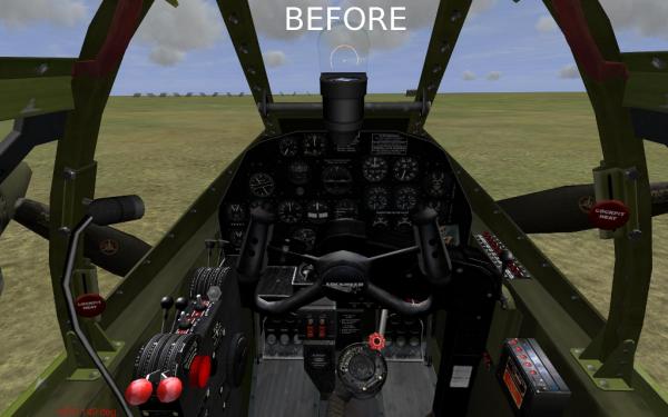
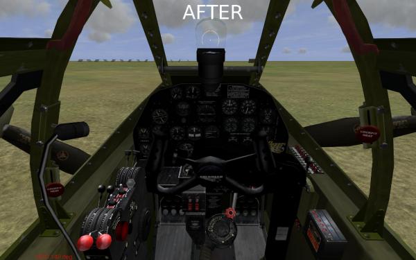
Ha, I didn't make this cockpit I just adjusted it a bit. I didn't like the cartoonishness of it. The colors and brightness where kind of off in my opinion. so I tried to tone it down a bit. Like I said, most people won't notice a difference from the pics but it's an improvement in game.
-
Did you get Double Pole Double Throw toggle?
-
Looks like the kits will run you from about 5500 to 15000. Thinking maybe another 4 to 5 thousand in other parts and tools maybe. Not sure if the skin for the wings comes in the kit but I hear it can be expensive. I'm pretty sure the kits don't come with the engine so not sure what a new engine cost. A used Piper Cub j3 1938 or so will run you around 25k to 40k. Then I guess you have to pay registration fees and all that mess. If you buy the 15k kit. It could run you 25 to 30K or more total I'm thinking.
-
No, he started a loop and at the top of it he ejected. While in mid air planeless, he shot the plane behind him with a Bazooka and then fell and re-entered his plane again. Probably staged but who knows.
-
Sorry if I wasn't as clear as I should be or if my explanation was confusing. Looking at my schematic again, its a bit rough. I just whipped it up real quick so I'll make you a better one. Your going to have 8 analog inputs as well so don't let them go to waste. The Bodnar boards are great for converting old flight systems like the old metal thrustmaster HOTAS and pedals to usb while improving performance. I have 5 unused analogs left on my board so I am thinking about making a custom dual throttle and pedals.Bodnar makes a 12 bit version of the board but based on the sensitivity of my trim controls I think the 10 bit version will be enough for any joystick. 10 bits is equal to 1024 steps of resolution across the full range of the axis. So from stick center to full left is 512 steps and from center to full right is 512 steps. Plenty I think.
-
Darkened some area, adjusted colors and added some filters. Took away a lot of the cheesiness. Just unzip to your #up# or mods folder. The screen shots don't do it a lot of justice. http://dangerdogz.com/forums/files/file/581-p38-cockpit-repaint-revised/
-
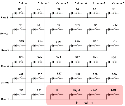
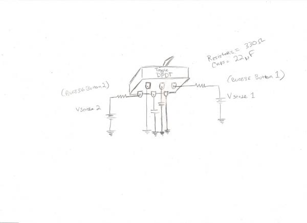
I labeled it (v sense) and wrote BU0836 over it where the 1v supply is shown. Its just a general representation of the boards voltage at the digital input pins. I don't know exactly how much voltage the board uses for the switch continuity check but typically its 5v or less for digital. For the sake of argument lets just say its 5v. When the circuit is closed, the 5v pin is shorted to the a ground pin. When the closed condition is detected by the integrated circuit on the BU0836 it sends the computer a signal indicating that a button press has been detected. You can hook the BU0836 up and check the voltage between the 5v sending and ground pins to get the exact value but it doesn't really matter too much as long as some given amount of continuity is detected. As for "the opto" (opto-isolator?), you shouldn't be needing one as we are not adding any voltage to the circuit other then what is native to the BU0836. If your worried about repeat keystrokes or switch debouncing I don't see it being an issue especially not the switch denouncing as the BU0836 doesn't seem to have much of a problem with it on my setup and I have the switches hooked up directly to the board. I'm sure it was thought of when designed. Looking at the drawing, didn't label the caps C1 and C2 but this should be obvious. You can label them if it makes it easier to follow. One lead of the cap C1 is attached to (through the switch) a resister and then to a 5v digital input pin of the BU0836. This is not to be confused with the 5v source pin on the board for lighting LED and whatnot. The other lead of the C1 cap will be attached to the digital input ground pin of the BU0836. When you latch the switch in the right direction direction, C1 will have voltage applied to it from the 5v pin of the BU0836. The cap will take 5 time constants to fully charge. One time constant will be determined by the value of C1 and the attached resistor. During the time it takes for the cap to fully charge a button press will be detected by the BU0836 as the circuit will effectively be closed. When the cap fully charges, it will have the same voltage potential as that between the 5v and ground pins thus canceling one another out and creating an open circuit at this point. The BU0836 will detect this open state as a release of the button. The C2 cap circuit will be close with the switch in its current position and any voltage that might have been previously stored on it will be discharged through the attached resistor. It will then be empty and ready for the switch to be throw in the opposite direction at which point the whole system will reverse. C1 as mentioned above will now effectively become C2. While one cap is charging the other will be discharged, back and forth, flip flopping with the toggling of the switch. So for a toggle control in the game, you get one pulse in one switch position and another pulse when the switch is flipped the other way. You can add a much smaller value resistor to the discharge leg if you'd like to accelerate the discharge speed. Trying to keep the it simple, the BU0836 digital inputs can be hooked up as this 5v digital input pin > to switch > to ground digital input pin You can hook up 12 buttons this way but frankly its a waste. If you hook it up in matrix form you can have 32 buttons but it requires more wiring and it is a bit more to wrap your mind around. I have mine in matrix form and it wasn't that that big of a deal, you just have to keep thing straight and not get confused. There are optional diodes you can use if you'd like. I forwent the diodes and haven't had a single problem. Hope this helps, let me know if you run into any problems.
-
Hey all, I, like many of you, use the 'modded clouds light" mod for IL-2. There's always been a couple of graphical inconsistancies that bothered me about them though, so, I finally decided to "fix" them. I soften up some of the rough edges, added some more blending and fix a few issues (other loose ends). The changes are subtle and may not be noticeable by some folks, but having a very close look at them I think most of you will hopefully agree its an improvement. http://dangerdogz.com/forums/files/file/580-modded-clouds-light-v2/
-
Ok there Jabo, the attached circuits should work fine. The first is for in game toggle assignments the second is for 2 different in game button assignments per switch. For the second circuit you might want to add some much smaller value resistor to the discharge circuit for the caps so that they discharge much faster then the other caps charging. The way I have it drawn now, you are just shorting the leads of the cap to discharge it which can be a little hard on them and may more may not lower the life of the caps. If you use standard electrolytic caps with say a 25v rating I don't think 5 volts or less is going to hurt them. Let me know what you think. As for LED indication you will probably need a separate circuit for sensing the state of the output. Maybe a transistor biased by the the output acting as a current control gate to the LED and you'll need to get something like .7 volts or more from somewhere. This is all off the top of my head so let me stew on it for a few and I'll see what I can come up with. P.S. Ok I think I am finally done editing this post now..... Edit. ok maybe I am not done editing. I just re read your last post Jabo and 2 things come to mind. As you said momentary toggles are easy and with the BU0836 trim is a cinch and really couldn't be easier either. Leo Bodnar really outdid himself with this interface board as it is really a work of Geniius, very elegant and well though out. All you have to do is hook up some 100K pots to the analog pins and your done. It senses the pots and calibrates for them automatically. His board requires no drivers as its in the firmware. Any analog or digital inputs that do not have a button or pot attached are automatically disabled so they don't show up in the driver screen thus avoiding clutter and confusion. You can even hook 2 or more of his boards together if I understand correctly. For the price you can't beat them and making them yourself is just masochistic.
-

Improve The Look Of Old Games (Depending On Your Taste)
Mayhem replied to Mayhem's topic in Jim's Place
yeah, just for the heck of it tried it with BF2 right off the bat and it works fine.


